General Purpose mm-wave/THz Imaging Tutorial
THZ Imaging Limitations Tutorial Lots of people ask me about why mm-wave and THz imaging hasn't taken off even thought it is described as the bright new future in so many publications and talks, so I've made this video to demonstrate some of the key challenges still holding is back. The tutorial shows some of the major *physical* limitations of mm-wave / THz imaging with a focus on security screening... (lousy transmission loss, specular and contrast dependence on incident radiation geometry, and low diversity of reflection coefficients). Note: these are all physical challenges of operating mm-wavelengths, so simply making higher power sources or lower noise detectors will not change the outcome. To overcome these limitations, solutions are needed at the system level and how the imagery is collected in the first place.
Summary mm-W / Thz Imaging efforts:
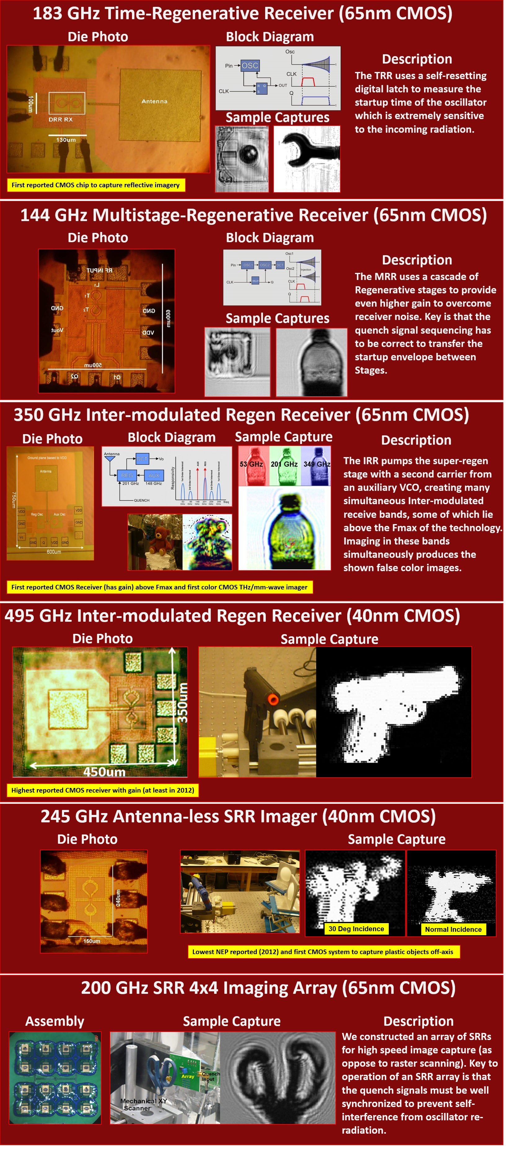
While many researchers have looked at mm-wave detectors (resistive self-mixing, plasmonic, or even LNA based) my PhD work focused on the super-regenertive receiver (SRRs) from Armstrong (RCA) in the 1930s as a detector for imaging. SRRs have several attractive features for narrow-band active imaging: they have gain all the way up to fmax, they are low power, and small (so you can build multi-pixel arrays). The major limitation is that they are essentially free-running VCOs so process variation, temperature and other variations cause them to become misaligned with the source frequency. They are also extremely narrowband (Q's beyond 10K) so frequency alignment is difficult. Using phase-lock loops to control the frequency really doesn't make sense since the VCO does not run continuously and is periodically interruped or quenched".
The imaging work demonstrated during my Ph.D. had 5 key contributions:
- Demonstration of a 183 GHz Time-Regenerative Reciver or TRR which uses a digital circuit to estimate the oscillator startup time and capture an image of incoming radiation.
- Demonstration of a 144 GHz Multi-stage Regenerative Receiver or MRR, showing that the super-regenerative from Armstrong could be extended to operate in multiple stages, providing even more RF gain.
- Demonstration of a 350 and 495 GHz Intermodulated-Regenerative Receiver or IRR, showing that the super-regenerative stage when pumped with a second carrier can provide operation above Fmax of the device and still provide adequate NEP/Resp for imaging.
- Demonstration of an antennaless imager at 245 GHz where the passive resonator of the super-regenerative stage is used to capture incoming radiation.
- Demonstration that these SRR receivers can operate in an array if their quenching conditions are correctly synchronized to avoid interference due to VCO re-radiation.
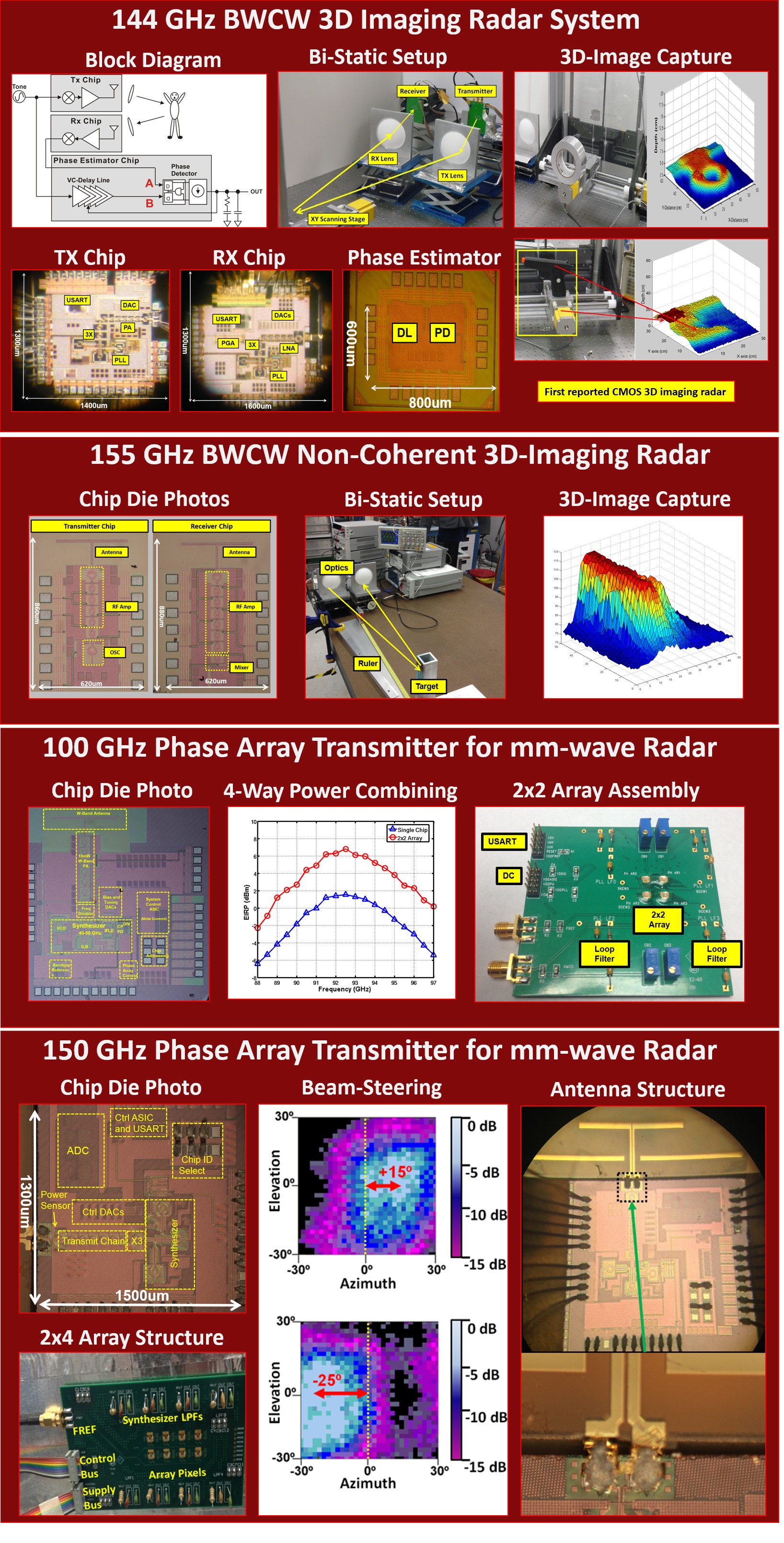
Summary of mm-W Imaging Radar Efforts:
The specular problems, geometric dependence on beam target angle and low reflection diversity has led many in the imaging community to consider radar as an alternative to SNR/power based active imaging. In imaging radar the time of flight (distance to the target) is used to develop contrast instead of reflected power, greatly breaking the dependence on the beam-target angle. In this work we demonstrated a coherent radar system at 144 GHz which uses successive binary weighted continuous wave (BWCW) sub-carriers to estimate the range to a target and capture an image from this time of flight estimation. We also demonstrated a non-coherent version of the BWCW at 155 GHz, as well as two phase arrays (100 and 150 GHz) that investigate the requirements of electronic steering for these radars. A video demo of the 144 GHz demonstration can be found here: radar_demo.
|